|
||||||||
Home > Product >Heat Load Calculation
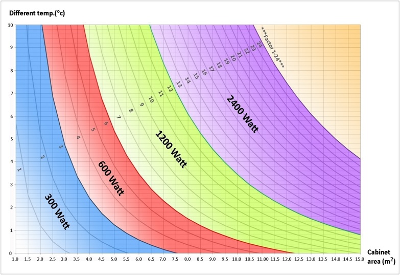
Fig.1 : Determination chart for DINDAN cooling unit. |
Click to go to heat load calculator |
|
|
|
1. Determination chart
Determination of cooling capacity is considered by Determination chart (Fig.1)
|
|
2. Nature of heat distribution
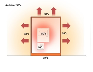
Heat normally generated inside the cabinet controller by operating equipments. Without cooling equipment, the temperature will be higher than its ambient and the heat inside will transfer out through the wall of cabinet. The temperature will balance by heat transfer as shown in Fig. 2.1, explaining the inverter working around 50°c and the smaller working at 40°c , while the total temperature inside is 37-39°c in most of cases
|
Fig. 2.1 : Illustration of heat distribution in cabinet before installation cooling unit. |
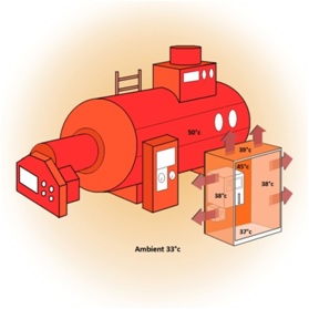
The top side of cabinet will shown higher temperature. How much heat transferring out depend on difference between temperature of the wall to ambient. In the case of more heat source such boiler stand at backside of cabinet making ambient only at the backside around 50°c as in Fig. 2.2 The heat will transfer in only in the area from backside of cabinet while the other side still transfer out. |
Fig. 2.2 : Heat distribution of cabinet with boiler is considered.
|
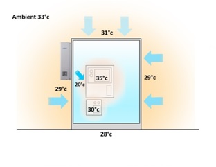
After installation of cooling unit the temperature inside keep lower than ambient. On the other hand, the heat will transfer back from its 33°c ambient to inside which is 28-31°c. Fig. 2.3 Illustrate the cooling unit supply air 20°c to cabinet which could maintain 28°c at bottom and 31°c at top of cabinet. Regarding to lower temperature have more higher mass weight. The higher ambient 33°c will make heat transfer back to the cabinet. While the inverter may operate at slightly higher than its cabinet which is 30-35°c. |
Fig. 2.3 : Illustration of heat distribution in cabinet after installation cooling unit.
|
|
3. For cabinet designer
Forecasting heat loss from equipment shall be employed when total area and average temperature are impossible. There should be consider two terms.
-Switching power supply, Inverter, Transformer, PLC, SCR, Monitor, Servo drive
Heat = H*A*dt
|
Heat = H*A*dt
|
|
4. Proper condition
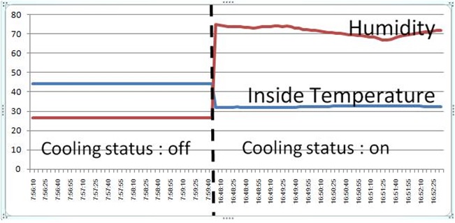
Temperature around 28-32°c should be maintain in the cabinet.As shown in fig.1 before cooling operation it is 45°c which is different to ambient 7°c and the area is 2.4 m2. As according to determination chart. |
Fig. 4.1 : example of temperature data collected between befor and after operation of cooling unit |
|
Measure the machine when it has been running for at least
20 minutes.
|
|